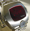
Alternate picture.

Red is positive, black is negative, 3 volts between the two.
Common plate of the two is
positive 1.5 volts.
For most modules you need the third lead for the 1.5 volts which is used to trigger the command, i.e. touch to the button contacts to simulate pressing a button. A better(IMO) solution for everyday quick testing of modules - keep an eye out for a back that uses two springs, put two batteries in the module, put the springs against the batteries and flip the whole package down on your bench - at that point, touching a metal object to the caseback and one of the contacts is the same as a button touching it.

Of course, you can also make a board with two springs sticking up that you connect your battery pack to...any number of ways to do this. Checking most modules with a battery pack is a bit cumbersome and frequnetly leads to various damage....like all the P4s that have broken connections from people pulling on the battery contacts whilst attaching clips.

The "springs protruding from board" method is infinately safer for those, imo.
http://www.retroleds.com -
Sales of vintage LED, LCD, analog watches,
parts and gadgets -
repair tutorials & tips
Nov. 2022 - back in business!! BItter divorce is in home stretch, come grabs some great deals, I had to open the safe . . . damn attorneys. piss.