It is currently 28 Apr 2024, 00:39


My (VERY COOL) Digital Clock needs some help

For electronic related stuff like module repair, silver epoxy fixes etc.
  • Author
  • Message
Offline
User avatar

dbmurphy

Nerd

Nerd

  • Posts: 49
  • Joined: 14 Dec 2006, 00:16

My (VERY COOL) Digital Clock needs some help

Post02 Feb 2011, 17:37

Hi All,

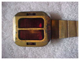
Last Summer, I snagged this offa' ebay. When it arived, it was kinda' working, but had a bunch of lamps out. I replaced most of them, and pul the clock up on the wall unit for a "burn in" test (funny thing is... this puppy runs REALLY hot).

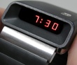
It ran for about a day, and then one of the segments went out. I tracked down the bad transistor, but I didn't have a replacement. I ordered a few from mouser, but they weren't right. I did get the segment to come back on, but it wouldn't go off when it was supposed to.

Anyways - now the clock isn't keping time correctly, i.e. the hour is not incrementing after it runs for a short while.

Is there anyone who will help me to repair this cool Digital??

I would be very willing to send it to someone, and pay for the work it needs.

Thanks SO much for reading and Best Regards,
Dennis
Image
Image
Offline

J Thomas

Wizard

Wizard

  • Posts: 410
  • Joined: 29 Jan 2008, 19:44

: My (VERY COOL) Digital Clock needs some help

Post02 Feb 2011, 17:49

:-D
Last edited by J Thomas on 30 Mar 2011, 08:12, edited 1 time in total.
Offline
User avatar

dbmurphy

Nerd

Nerd

  • Posts: 49
  • Joined: 14 Dec 2006, 00:16

: My (VERY COOL) Digital Clock needs some help

Post02 Feb 2011, 18:22

Yay Nixie-San !!!!

OK it's opened up and I got my DMM ready.

I have a OzziFox mini scope, so I hope that will work ok for what we are trying to do !
Offline
User avatar

Old Tom

Wizard

Wizard

  • Posts: 274
  • Joined: 15 Dec 2006, 10:48
  • Location: London, England

: My (VERY COOL) Digital Clock needs some help

Post02 Feb 2011, 19:11

Photo of circuit board would be good- are the displays individual light guide segments lit by small bulbs (looks to be too large for Minitrons and seems to be filament rather than LED/VFD/Nixie)? How big is the clock?
Offline

J Thomas

Wizard

Wizard

  • Posts: 410
  • Joined: 29 Jan 2008, 19:44

Re: : My (VERY COOL) Digital Clock needs some help

Post02 Feb 2011, 19:36

:-D
Last edited by J Thomas on 30 Mar 2011, 08:12, edited 1 time in total.
Offline
User avatar

dbmurphy

Nerd

Nerd

  • Posts: 49
  • Joined: 14 Dec 2006, 00:16

: My (VERY COOL) Digital Clock needs some help

Post02 Feb 2011, 19:45

Yes! Good "eye" these are filament bulbs, and the clock housing is a 9" x 9" cube.

Here are some "snaps"
Image
Image
Image
Image

sorry for the blur in the last one :(
Offline
User avatar

dbmurphy

Nerd

Nerd

  • Posts: 49
  • Joined: 14 Dec 2006, 00:16

: My (VERY COOL) Digital Clock needs some help

Post02 Feb 2011, 19:49

Thanks Jeff,

I'll check that "can" later today, and I'll take a photo of the bad transistor. Maybe you guys can help me figure out what a suitable replacement would be?
Offline

J Thomas

Wizard

Wizard

  • Posts: 410
  • Joined: 29 Jan 2008, 19:44

Re: : My (VERY COOL) Digital Clock needs some help

Post02 Feb 2011, 20:27

:-D
Last edited by J Thomas on 30 Mar 2011, 08:12, edited 2 times in total.
Offline
User avatar

egomon

Techie

Techie

  • Posts: 230
  • Joined: 03 Jan 2010, 12:04

: My (VERY COOL) Digital Clock needs some help

Post02 Feb 2011, 21:36

I WANT ONE............
Offline
User avatar

dbmurphy

Nerd

Nerd

  • Posts: 49
  • Joined: 14 Dec 2006, 00:16

: My (VERY COOL) Digital Clock needs some help

Post02 Feb 2011, 23:39

Yeah there is a whole army of transistors in a row, and this thing could double as a space heater :eek: .

Well, y'know..... the bulbs don't seem extra bright, for some reason my camera made it look really bright, but, in fact, they are not as bright as they appear in the images.

Is it possible that I used the wrong bulbs when I was replacing? Could that cause issues?

Provided I can figure out my scope :-D I should have a report back very soon.

Thanks SO much for the assist guys!
Offline
User avatar

Old Tom

Wizard

Wizard

  • Posts: 274
  • Joined: 15 Dec 2006, 10:48
  • Location: London, England

: My (VERY COOL) Digital Clock needs some help

Post03 Feb 2011, 18:51

Looking at the board I suspect (can't read the chip numbers) you have 7448 bcd to 7 segment decoders directly driving the bulb transistors (thought you might have had buffer chips in there but tracing out the board shows those top seven ics are more likely 3 counters, 3 decoders and a gate chip to handle the 12 count). In which case they are probably 2N3704/5 types (TO92 case, 800mA max current- the ..04 is a higher gain group and would be a better choice than the ..05). Best way to be absolutely sure is to unsolder a known good transistor and use a transistor tester on it.

And don't forget to check the regulators are giving 5 volts, TTL loves to misbehave especially with higher voltages.

Are the bulbs wire ended or do they screw in- screw ins almost always have the rated voltge and current embossed in tiny letters around the screw cap.
Offline
User avatar

dbmurphy

Nerd

Nerd

  • Posts: 49
  • Joined: 14 Dec 2006, 00:16

: My (VERY COOL) Digital Clock needs some help

Post03 Feb 2011, 19:17

I de-soldered the offending transistor (visually traced back from segment that is out). It reads SPS6725 (with what looks to be a Motorola "symbol" in front). I wasn't able to match this, and ended up buying a 2N6725 - but it didn't work !!!

Sadly - I do not have a transistor tester

As part of "bad segment" troubleshooting... I swapped the bad one with a working one from the board, and the problem followed - ergo bad transistor right?

I also put a TIP102 there just to see what would happen (maybe didn't work without a pre-driver), and the segment lit up, but never turned of when it was supposed to.

I'll post the chip #s tonight, and check the output from the voltage regulators.

Thanks Guys !!!! I REALLY appreciate the guidance. We'll get this baby working again :mrgreen:
Offline
User avatar

dbmurphy

Nerd

Nerd

  • Posts: 49
  • Joined: 14 Dec 2006, 00:16

: My (VERY COOL) Digital Clock needs some help

Post03 Feb 2011, 22:03

Forgot to answer Tom's Q about the bulbs, they ARE wire ended, the best way to describe them is they are like larger versions of mini x-mas replacement lamps.

The main problem while I was replacing the lamps, was that the wire legs on these lamps were REALLY brittle, and the smallest nudge would break the wire.

I used #555 pinball machine bulbs as replacements, as they worked with a similar brightness, and I had a lot on-hand :)
Offline

J Thomas

Wizard

Wizard

  • Posts: 410
  • Joined: 29 Jan 2008, 19:44

Re: : My (VERY COOL) Digital Clock needs some help

Post03 Feb 2011, 22:39

:-D
Last edited by J Thomas on 30 Mar 2011, 08:11, edited 1 time in total.
Offline
User avatar

dbmurphy

Nerd

Nerd

  • Posts: 49
  • Joined: 14 Dec 2006, 00:16

: My (VERY COOL) Digital Clock needs some help

Post03 Feb 2011, 22:54

Right after dinner ~6:30pm I'm gonna go to the workbench, so I'll have a report tonight before 8pm.
Offline
User avatar

dbmurphy

Nerd

Nerd

  • Posts: 49
  • Joined: 14 Dec 2006, 00:16

: My (VERY COOL) Digital Clock needs some help

Post04 Feb 2011, 17:14

Good Morning,

I realized last night that the clock was going to be hard to work on with the tight tolerances, so I had to "split it apart". I created a test rig, so that I can work on it easier.
Image

Here are some better pics of the board too
UPPER LEFT
Image
UPPER RIGHT
Image
LOWER RIGHT
Image


Before I do the wrong things.... I have a few questions.

First - measure the voltage from the regulators I am not quite sure where they are. I am familiar with the kind that look like transistors, but is this what hey look like (sorry for the ignorance)
Image

I'll get the scope on the cap in a little while provided I can figure that all out ;) Are you guys at all familiar with the OsziFox ??
Offline
User avatar

rewolf

Guru

Guru

  • Posts: 1863
  • Joined: 11 Jul 2004, 15:32
  • Location: Ravensburg, Southern Germany

: My (VERY COOL) Digital Clock needs some help

Post04 Feb 2011, 19:28

Yout last picture does show a voltage regulator, datasheet is here: http://www.national.com/mpf/LM/LM323.html#Overview
It's in the rather ancient TO-3 package, formerly used for power transistors as well.
Offline
User avatar

Old Tom

Wizard

Wizard

  • Posts: 274
  • Joined: 15 Dec 2006, 10:48
  • Location: London, England

: My (VERY COOL) Digital Clock needs some help

Post04 Feb 2011, 20:31

LM323K was a fixed voltage (5 volts) 3amp regulator and you have two (!) of them on the back plate. Tracing out the circuit it looks like all these do is supply current to the bulbs- assuming 6v 100mA bulbs atime of 12:58 would draw (3*.1*20) amps or 6 amps!.

Looking at your lower right photo, next to the 7400, I see something that looks suspiciously like a TO220 cased power transistor (might be a 7805 type regulator) which has been dissipating a lot of heat- I think this is the regulator for the +5 volt supply to the logic and is separate from the bulb supply and this should be investigated first.

As an aside the date codes on the chips are remarkably tight and date to autumn (fall for the colonials) of 1971 so this clock was probably assembled early 1972.
Offline
User avatar

dbmurphy

Nerd

Nerd

  • Posts: 49
  • Joined: 14 Dec 2006, 00:16

: My (VERY COOL) Digital Clock needs some help

Post04 Feb 2011, 21:12

OKAY !!! APOLOGIES for the confusion. the LM323K was just one I had laying around, and took the photo for package ID only. The two regulators that are on the backplate of the clock are 2N3611 (139)., and they are near the main transformer, I measured them, but the voltage they were supplying was WAY over 5v and I got suspicious that they were doing something else. It makes sense that they supply the bulb power, as I seemed to be getting somewhere between 12-13v out of them while the clock was on. What was weird is that they started out around 9v and crept up to 12/13v (weird)

BINGO! Good "eye" again Tom 8-)
I Looked at the thing next to the 7400, and on the other side of the board... HUGE heat sink, and here is what was behind it. (nice wayward solder blob there too LOL)

Unless I miss my guess... THAT should be supplying the 5V to the logic circuit no ?

Where should I take the reading? I mean which pins?

Thanks!
Image


PS - I think the #555 bulbs that I was using as replacements were 6.3v .25amp I hope that this is ok :( I am getting concerned that the ones I used are drawing too much power !!!!!

Cheers,
Dennis
Offline
User avatar

egomon

Techie

Techie

  • Posts: 230
  • Joined: 03 Jan 2010, 12:04

: My (VERY COOL) Digital Clock needs some help

Post06 Feb 2011, 13:18

Hi. How common the "computa" clock is? It is so beatiful - I WANT ONE. How often they show up on ebay? Where else to loock for this clock?

Regards Egon
Offline
User avatar

dbmurphy

Nerd

Nerd

  • Posts: 49
  • Joined: 14 Dec 2006, 00:16

: My (VERY COOL) Digital Clock needs some help

Post06 Feb 2011, 16:26

Honestly...... I have been shopping on ebay since 1997, and this was the only one I ever saw.
Offline
User avatar

Old Tom

Wizard

Wizard

  • Posts: 274
  • Joined: 15 Dec 2006, 10:48
  • Location: London, England

: My (VERY COOL) Digital Clock needs some help

Post06 Feb 2011, 18:14

The 2N3611s are ordinary transistors so probably being used as series regulators- voltage should not have crept up like that, indicative of dried out capacitor somewhere. They usually fit a pair to the base, one small ceramic, one electrolytic and the electrolytic wil be the problem (typical value 47-100uF).

The TO220 down by the logic chips is probably another transistor rather than a regulator and should supply 5 volts to the ICs- measure on the 7400 adjacent (pin 14 is +5v, pin 7 is gnd if I remember rightly). Having sorted this out time to see why the hour digit no longer rolls over- does it roll over when you use the setting switch? Logic probe helps here to see whats going high and whats not! The transistions are too slow for an oscilloscope to be of much use (you could use it to check the 60Hz line frequency is being squared up properly and trace it throught the pre-display counters bottom left).

@Egomon

I would suspect this clock was sold in the North American market only - it has no provision for switching over to the 50Hz line frequency used in Europe.

If you want a cool European nixie clock try hunting down one of the UK made Timeon clocks- I have seen three different types, two four digit and one six digit (with alarm).
Next

Return to Electronical

Who is online

Users browsing this forum: No registered users and 84 guests