It is currently 11 May 2024, 16:00


Beltime Button Push Repair

For electronic related stuff like module repair, silver epoxy fixes etc.
  • Author
  • Message
Offline
User avatar

Caruso

Wizard

Wizard

  • Posts: 323
  • Joined: 27 Aug 2011, 12:25

Beltime Button Push Repair

Post29 Feb 2012, 21:15

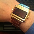
I bought this Beltime watch a while ago in a non working state for very little £. I used the bracelet on the working Beltime I have in my avatar.

Now I thought I'd have a go at getting the module working in the donor watch. It didn't work with new batteries, so my next thought was the button push. Upon examination of the module it has a rubber like substance where I would normally expect to see metal contacts at the 1 and 3 o'clock positions. Through experimentation I have found that if I touch the metal contact on the face of the module with a screwdriver whilst touching the battery cover on the back, then the circuit is complete and the module lights up.

In this pic you can see the contact circled in red.
Image
http://thumbsnap.com/uhrLkQIZ

Further experimentation has shown that pushing the rubber contact against the inside face of the module which has a corresponding contact also causes the module to light. It doesn't like it if I clip a probe and clip to the battery cover and touch the contact - it seems to prefer a lot of resistance in that circuit.

The problem is that the rubber pieces that form the resistant part of the circuit have perished and don't have the desired effect from a regular button push. In this pic you can see the better rubber in the module and the more broken one lying outside next to it, both circled in red.

Image
http://thumbsnap.com/eXyliTKE

Has anyone seen such a thing before? Do you know what I could use to replace the old rubbers?
Check out my vintage digital channel on YouTube:
http://www.youtube.com/user/danhay1137
Offline

Ole Joe

Geek

Geek

  • Posts: 96
  • Joined: 05 Dec 2011, 19:05
  • Location: Huntington Beach, CA

Re: Beltime Button Push Repair

Post29 Feb 2012, 22:08

Hello Caruso,

I just happen to have a small plastic box full of those silver bearing rubber contacts for that Frontier Module. PM with your mailing address and I'll send you some. I'm surprised to see that the module is an FR - 015. That was one of the very last LED chips that was designed before Frontier went LCD. I wasn't aware that they even made it to production. It's a good chip, as everything is integrated into one IC. By the way, the contacts have a chamfer on one end. The contact is inserted with the chamfer at the top and facing outward.
Offline
User avatar

Caruso

Wizard

Wizard

  • Posts: 323
  • Joined: 27 Aug 2011, 12:25

Re: Beltime Button Push Repair

Post29 Feb 2012, 22:21

Ole Joe wrote:Hello Caruso,

I just happen to have a small plastic box full of those silver bearing rubber contacts for that Frontier Module. PM with your mailing address and I'll send you some. I'm surprised to see that the module is an FR - 015. That was one of the very last LED chips that was designed before Frontier went LCD. I wasn't aware that they even made it to production. It's a good chip, as everything is integrated into one IC. By the way, the contacts have a chamfer on one end. The contact is inserted with the chamfer at the top and facing outward.
Wow, thanks for that info and the offer. I'll send a PM shortly.

I'm able to set the time and date with my workaround, so I know the module is ok but just the button pushes that don't work.

The module is very simple, once you get it apart. There is a board with battery contacts, the quartz oscillator and a trimmer on 1 side, then the display and the IC under the black plastic blob on the other side...very straightforward. It's housed in a plastic case that holds the rubber bearing contacts and locates the module within the watch itself.
Check out my vintage digital channel on YouTube:
http://www.youtube.com/user/danhay1137
Offline

Ole Joe

Geek

Geek

  • Posts: 96
  • Joined: 05 Dec 2011, 19:05
  • Location: Huntington Beach, CA

Re: Beltime Button Push Repair

Post01 Mar 2012, 02:57

Hello Caruso,

Please read through the entire instructions listed before doing anything.

While you've got the watch module apart, remove the ceramic substrate from the carrier ring. Handle carefully and avoid touching the "black blob" coating that covers the Integrated Circuit. This coating protects the circuit and the wire bonds from the IC to the substrate. With a small piece of 3M Scotch Brite scrubbing pad, or equivalent, clean the contact pads on the substrate that make contact with the silver bearing rubber. The Palladium Silver used to inerconnect the various parts of the circuitry oxidize big time over a period of 35+ years. Also, give the battery contacts a good scrubbing too while you are at it.

When your ready to put the module back together, insert the substrate into the plastic carrier ring and align the notch in the ceramic substrate with the guide pin of the plastic carrier. The guide pin in the plastic carrier is located at about the 10:00 o'clock position. This notch/guide pin provides proper alignment for the substrate into the carrier ring. Ensure that the substrate is under the lip molded into the carrier ring at the 11:00 o'clock position. With the end of a ball point pen or similar object, press down on the ceramic substrate at about the 5:00 o'clock position until the ceramic substrate is seated and locked by the carrier latch. You may have to force the plastic latch outward to get the ceramic substrate down into the latched position. Be gentle if this is necessary and make sure the latch lip is locking the substrate into the carrier.

The conductive rubber contacts do not make firm contact with the ceramic substrate pads if the top plactic cover is not installed. When you re-install the top cover, start by inserting the cover "ear" located at the 2:00 o'clock position so that it is engaged under the plastic latch of the carrier ring. You will have to put some downward pressure on the cover to fully engage the ear under the latch. Make sure the cover ear is seated under the latch before going further. Next, press down on the cover at the 9:30 position and seat the cover ear under its latch. You may have to gently pull the plastic latch outward to get the ear to engage. Be very gentle if this is necessary. The last step involves pressing down on the top cover at the 6:00 o'clock position and engaging the top cover ear into the plastic carrier latch. Make sure that the two small ears at the top of plastic carrier substrate latch at the 5:00 o'clock position are inside the top cover before engaging the 6:00 top cover latch.

A simple fixture for testing Frontier modules outside the watch case is too simply install the batteries and battery clip. Lay the moudle down on a small piece of metal, copper clad printed circuit board, brass etc., so that the battery clip is making contact with the metal. Using a small clip lead or soldered wire to the metal plate, touch the other end of the wire to the rubber contacts of the module. You will be able to control all functions with this simple method. As a CAUTION, do not attempt using this method with a Frontier Alarm Module, FR2007.

Hope this helps,

Joe
Offline
User avatar

Caruso

Wizard

Wizard

  • Posts: 323
  • Joined: 27 Aug 2011, 12:25

Re: Beltime Button Push Repair

Post06 Mar 2012, 20:49

Joe,

the silver rubber contacts arrived today. Thank you so much for sending them, it really reaffirms my faith in human nature.

Dan
Check out my vintage digital channel on YouTube:
http://www.youtube.com/user/danhay1137
Offline

Ole Joe

Geek

Geek

  • Posts: 96
  • Joined: 05 Dec 2011, 19:05
  • Location: Huntington Beach, CA

Re: Beltime Button Push Repair

Post06 Mar 2012, 21:06

Caruso wrote:Joe,

the silver rubber contacts arrived today. Thank you so much for sending them, it really reaffirms my faith in human nature.

Dan


Your welcome Dan, glad I could help you out.

Joe

Return to Electronical

Who is online

Users browsing this forum: No registered users and 45 guests