


Hi jdexter.
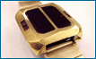
The hole you are talking about is where the potting gel was injected I believe.
I'm not sure I understand what you're after with the 'farrad rating' requirement. Each battery was originally 50mAh if that helps.
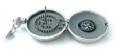
I believe most of the cases were SS, but I think i did read somewhere that they did experiment with chromed base metal at some stage. There were also solid gold, gold plated, black ceramic and titanium.
Just found this post, which outlines case types:
http://www.dwf.nu/viewtopic.php?p=16575 ... 27bf8b34b9
Rgds,
Andrew.
It is currently 11 May 2024, 10:45
It' here!
30 posts
• Page 1 of 2 • 1, 2


Guru

- Posts: 3636
- Joined: 04 Feb 2006, 10:34
- Location: Surrounded by hicks and sticks (farms and woods) - Michigan,USA
Guru
- Posts: 3636
- Joined: 04 Feb 2006, 10:34
- Location: Surrounded by hicks and sticks (farms and woods) - Michigan,USA


Guru
- Posts: 3636
- Joined: 04 Feb 2006, 10:34
- Location: Surrounded by hicks and sticks (farms and woods) - Michigan,USA
Guru
- Posts: 3636
- Joined: 04 Feb 2006, 10:34
- Location: Surrounded by hicks and sticks (farms and woods) - Michigan,USA
30 posts
• Page 1 of 2 • 1, 2
Who is online
Users browsing this forum: No registered users and 7 guests