It is currently 27 Apr 2024, 21:24


dot matrix mkII

  • Author
  • Message
Offline
User avatar

clockace

Techno Mage

Techno Mage

  • Posts: 544
  • Joined: 25 Feb 2008, 03:28
  • Location: Arizona

dot matrix mkII

Post06 Apr 2009, 21:36

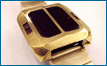
time for a new post and update. i have been working with my second dot mkII. i has been a challenge. besides the usual sc, qc, replacements, this one has serious corrosion under the sc. it was filled with the "snotty gel" which is not as good for protecting from corrosion as the hard gel. there were 4 traces from the chip tabs to their connecting segment transistors and other points. the tabs on the chip were all in fairly good shape. i used silver epoxy to repair the traces/connections. that is a delicate job to do w/o shorting 2 traces/tabs with too much epoxy. however, i got everything to lite up and it was running. it kept dying on me even while trying to set it. i could not imagine what the problem might be, so i unsoldered and reset all 4 reeds so they faced properly towards the outside of the pcb. they were quite far off originally as much as 180 degrees. howard said that didn't really matter, but i felt it couldn't hurt to put them right. i had the same problem, however. it would lite up for awhile and them go dead. sometimes it stopped keeping time and others it kept time just wouldn't lite up. finally i thought why don't i check the power. i put the volt meter to the cells and turned on the display. and watched the cells go down rapidly. i changed the sc for a new one i got from howard and charged it fully. it is now working w/o dying. i was thinking, there is a diode that keeps the cells from discharging back thru the sc. can the diode be at fault? how can i check the diode to see if it is working properly?
Offline
User avatar

charger105

Guru

Guru

  • Posts: 867
  • Joined: 02 Mar 2007, 02:11
  • Location: Australia

: dot matrix mkII

Post07 Apr 2009, 05:54

Hi Peter.
You can check the diode easily with your multimeter if it's got a diode continuity test mode (most do).
It should measure about 0.6V in one direction, and open circuit in the other.
See here for an explanation:

http://www.allaboutcircuits.com/vol_3/chpt_4/3.html

Rgds,
Andrew.
Offline
User avatar

charger105

Guru

Guru

  • Posts: 867
  • Joined: 02 Mar 2007, 02:11
  • Location: Australia

: dot matrix mkII

Post07 Apr 2009, 13:28

In your situation, another way to check if the batteries are discharging through the SC, would be to disconnect the SC, and see if you can measure the battery voltage at the SC attachment points on the board. If the diode is functioning, you should not see the 3V.
Conversely, sith the SC re-attached (and under a light), you should see 3V at the battery attachment points.

I hope this helps Peter.
Rgds.
Offline
User avatar

clockace

Techno Mage

Techno Mage

  • Posts: 544
  • Joined: 25 Feb 2008, 03:28
  • Location: Arizona

: dot matrix mkII

Post07 Apr 2009, 23:56

andrew, i like that suggestion. i can understand it. the first one went over my head, especially since i don't have that kind of meter. my meter only measures volts [dc/ac] ohms, and microamperes. i think that is what the last one is. it has a funny upsidedown u symbol with a leg on it. it is made for working on the early citizen electronic watches, but it is not too sophisicated. i will try your last suggestion tonight. thx., peter
Offline
User avatar

clockace

Techno Mage

Techno Mage

  • Posts: 544
  • Joined: 25 Feb 2008, 03:28
  • Location: Arizona

: dot matrix mkII

Post09 Apr 2009, 03:19

well, i disconnected the minus end of the sc. voltage meter from plus end to solder pad of minus end reads "0". reconnected minus end to solder pad. now reads 2.8v. i guess the diode is working. i kind of thought it was. i think my problem is something else. i and mike[sully108] seem to have similar problems. answers?????? suggestions????? :-? peter

Return to Synchronar

Who is online

Users browsing this forum: No registered users and 11 guests