It is currently 28 Apr 2024, 06:41


Synchronar Mark I - Where's the problem??

  • Author
  • Message
Offline
User avatar

renozumi

Member

Member

  • Posts: 24
  • Joined: 02 Oct 2009, 21:39
  • Location: Berne, Switzerland

Synchronar Mark I - Where's the problem??

Post02 Oct 2009, 22:14

Hi.

Today I tried to change the batteries for my Synchronar Mark I. Everything went well ! I opened the case without damage, the batteries inside looked not bad. So i putted the watch on an 3V source ? but nothing happend ;-(

It is really a great watch and I makes me sad, that it wont run.

Can someone help me ?

Bye
Reno
Offline
User avatar

retroleds

Guru

Guru

  • Posts: 3636
  • Joined: 04 Feb 2006, 10:34
  • Location: Surrounded by hicks and sticks (farms and woods) - Michigan,USA

: Synchronar Mark I - Where's the problem??

Post02 Oct 2009, 22:23

Reno:
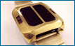
You understand that the watch is activated by the cylindrical magnets that are moved by the switches? So, you will have to wave a small magnet along those tracks where the switches lay, in order to activate the watch. If it is still functional

And you are sure you have the polarity corect, a guy could get screwed up, between the batteries being linked together and the mess of the potting gel.....attach a VOM meter to the leads and hold up to a bright light, as a double check.
http://www.retroleds.com - Sales of vintage LED, LCD, analog watches, parts and gadgets - repair tutorials & tips
Nov. 2022 - back in business!! BItter divorce is in home stretch, come grabs some great deals, I had to open the safe . . . damn attorneys. piss.
Offline
User avatar

renozumi

Member

Member

  • Posts: 24
  • Joined: 02 Oct 2009, 21:39
  • Location: Berne, Switzerland

: Synchronar Mark I - Where's the problem??

Post03 Oct 2009, 17:57

Hi. Thank you for your answer. But these points were ok. I noticed, that on the board where not all the switches installed that where used for the reed switch. So on the one side where two and on the other side was 1 installed. on the rear side was only one installed. Could that be the problem, how many of them must be on the board? Bye and thanks Renato
Offline
User avatar

retroleds

Guru

Guru

  • Posts: 3636
  • Joined: 04 Feb 2006, 10:34
  • Location: Surrounded by hicks and sticks (farms and woods) - Michigan,USA

: Synchronar Mark I - Where's the problem??

Post03 Oct 2009, 18:05

Depends which model the module is. The single reed switch at rear was correct on some models. Others had none there, and finally some had two.

Not sure how anyone can say/know what model they have with Synchronars, since the differences were fairly poorly documented, the cases are unmarked, and the feature set seemed to be in constant flux.
http://www.retroleds.com - Sales of vintage LED, LCD, analog watches, parts and gadgets - repair tutorials & tips
Nov. 2022 - back in business!! BItter divorce is in home stretch, come grabs some great deals, I had to open the safe . . . damn attorneys. piss.
Offline
User avatar

clockace

Techno Mage

Techno Mage

  • Posts: 544
  • Joined: 25 Feb 2008, 03:28
  • Location: Arizona

: Synchronar Mark I - Where's the problem??

Post03 Oct 2009, 21:01

your problem is probably the qc. the first thing i would do is replace it. i have several early models with only 4 reeds. they are dot matrix display. 2 reeds on the right, 1 reed on the left towards you, and 1 reed on the rear on the right side with the display facing you. i think you have all the switches necessary. replace the qc and see what happens. :-) peter
Offline
User avatar

renozumi

Member

Member

  • Posts: 24
  • Joined: 02 Oct 2009, 21:39
  • Location: Berne, Switzerland

: Synchronar Mark I - Where's the problem??

Post03 Oct 2009, 21:44

Sorry, but what's the "qc" ;-)


Thanks and bye
Renato
Offline
User avatar

bucko170

Guru

Guru

  • Posts: 3647
  • Joined: 20 Oct 2007, 11:47
  • Location: Nottinghamshire: The Home of Robin Hood..... UK

: Synchronar Mark I - Where's the problem??

Post03 Oct 2009, 21:51

QC = Quartz Crystal
Offline
User avatar

clockace

Techno Mage

Techno Mage

  • Posts: 544
  • Joined: 25 Feb 2008, 03:28
  • Location: Arizona

: Synchronar Mark I - Where's the problem??

Post04 Oct 2009, 00:06

can you post some photos? the quartz crystal[qc] is impossible to change w/o removing the circuitry from the red top. that will more than likely create some other challenges, but i would bet that the qc is the problem. where are you located? peter
Offline
User avatar

renozumi

Member

Member

  • Posts: 24
  • Joined: 02 Oct 2009, 21:39
  • Location: Berne, Switzerland

: Synchronar Mark I - Where's the problem??

Post04 Oct 2009, 08:19

Hi Peter. I already removed the board from the red top, with the discribed problems...

I posted some photos: The pictures with a single board was the board I posted the problems. The other pictures shows some spare parts. I'm located in Switzerland.

Thanks for your help and bye
Reno


http://www.majhost.com/cgi-bin/gallery.cgi?f=212907
Offline
User avatar

charger105

Guru

Guru

  • Posts: 867
  • Joined: 02 Mar 2007, 02:11
  • Location: Australia

: Synchronar Mark I - Where's the problem??

Post04 Oct 2009, 13:54

Hi Reno.

There looks to be quite a bit of corrosion on this board. For a start, 3 of the 4 digit transistors are missing, and the 4th looks a bit messy. Most of the segment transistors (the other 7)have green stuff growing underneath, so you've got your work cut out !

You'll have to get the digit transistors put back on before you'll see anything. They're the little black dome-shaped things.

Did this come out of an unopened case.......it looks like it may have been floating around in a parts box for a while.

Rgds,
Andrew.
Offline
User avatar

renozumi

Member

Member

  • Posts: 24
  • Joined: 02 Oct 2009, 21:39
  • Location: Berne, Switzerland

: Synchronar Mark I - Where's the problem??

Post04 Oct 2009, 17:32

Hi. Thanks a lot. I'm asking myself how the transistors can be missed. The red cases was sealed and not opened and in the case there where no transistors. But how can i remove the corrosion?

Bye
Renao
Offline
User avatar

clockace

Techno Mage

Techno Mage

  • Posts: 544
  • Joined: 25 Feb 2008, 03:28
  • Location: Arizona

: Synchronar Mark I - Where's the problem??

Post04 Oct 2009, 17:39

ooooohhhhh, that looks pretty far gone. i would forget about that one and work with one of the other cleaner pcb's. there are some nice dot matrix displays there also. with careful unsoldering and resoldering you could take the chip off one of the cruddy ones and resolder to a clean one. you have a real challenge on your hands, but you might just get one working. :-) peter
Offline
User avatar

renozumi

Member

Member

  • Posts: 24
  • Joined: 02 Oct 2009, 21:39
  • Location: Berne, Switzerland

: Synchronar Mark I - Where's the problem??

Post04 Oct 2009, 17:55

Thank you Peter! I'll be glad to do this work ;-)

I will see for another board but it's difficult to decide because on every board it seems something missing...

Bye
Renato
Offline
User avatar

charger105

Guru

Guru

  • Posts: 867
  • Joined: 02 Mar 2007, 02:11
  • Location: Australia

: Synchronar Mark I - Where's the problem??

Post05 Oct 2009, 05:15

I agree with clockace, this board will be very difficult to get working again. The transistors probably came away when you scraped the potting gel off, or when you removed the solar panel.

Most of the other boards have the oscillator resistors and diode 'pulled' out (possibly with pliers !). It damges the board and makes it tricky to re-attach. The one on the bottom right of the 3rd picture looks hopeful. Only the display looks missing. As a test, try attaching on of your new displays with the long gold legs still in place, to make it easier (there should be an arrow on the back of the display which should point down in the correct orientation).

Rgds,
Andrew.
Offline
User avatar

clockace

Techno Mage

Techno Mage

  • Posts: 544
  • Joined: 25 Feb 2008, 03:28
  • Location: Arizona

: Synchronar Mark I - Where's the problem??

Post05 Oct 2009, 06:51

it's hard to tell what is useful on the last 2 photos without seeing both sides of the pcb's. it looks like you will still need to get quartz crystals, solar cells, reed switches, do you have the sliders and magnets? where did you find all that stuff? i agree that it looks like it came from a scrap box. with some skillful soldering and parts from one to another something good might happen. some of the chips look like they have all 21 legs in decent condition and some of the pcb's look useable but you seem to be lacking the posts that the reeds solder onto, among other parts. you had better study all of them carefully and try to find the best parts of each and try to make 1 good one. it looks like you have 2 brand new unused displays and they look like the dot matrix version. wish you the best. peter
Offline
User avatar

renozumi

Member

Member

  • Posts: 24
  • Joined: 02 Oct 2009, 21:39
  • Location: Berne, Switzerland

: Synchronar Mark I - Where's the problem??

Post05 Oct 2009, 09:28

Hi. That's a great community - thanks for all your hints!!!

I bought this part from Barry Riehl. He sells this parts on Ebay. I have made some high res. pictures on:

http://www.majhost.com/cgi-bin/gallery.cgi?f=212907

Board 11 is the one I posted the problems...

Bye Reno
Last edited by renozumi on 05 Oct 2009, 11:13, edited 4 times in total.
Offline
User avatar

renozumi

Member

Member

  • Posts: 24
  • Joined: 02 Oct 2009, 21:39
  • Location: Berne, Switzerland

: Synchronar Mark I - Where's the problem??

Post05 Oct 2009, 09:28

Hi. That's a great community - thanks for all your hints!!!

I bought this part from Barry Riehl. He sells this parts on Ebay. I have made some high res. pictures on:

[url]http://www.majhost.com/cgi-bin/gallery.cgi?f=212907

It's not easy to decide...

Bye Reno[/url]
Offline
User avatar

Sully008

Wizard

Wizard

  • Posts: 289
  • Joined: 14 Oct 2008, 18:19
  • Location: Wpg, Mb. Canada

Re: : Synchronar Mark I - Where's the problem??

Post05 Oct 2009, 19:11

Hi Reno,

Welcome to the forums! I've bought quite a few parts from Barry. His stuff is hit 'n miss, especially with the MkIII stuff. I have managed to get some of the MkI/II boards working.

Your #11 board looks to be beyond simple repair. I think your best bet would be to transfer reed switches and display onto board #2, since the posts for the switches are all there, and it looks to be the cleanest. You will need to solder a new display and quartz crystal on though. Best of luck! We're here if you need help.

EDIT: Board 2 is missing one of the reed switch posts, not impossible to fix, but not easy either.

Board 10 is missing the resistors on the bottom side, the QC and the chip. But all the switches and display are attached. Again, all three are not terribly difficult to solder in, but does require a steady hand. Plus the possibility of frying the chip while desoldering/soldering is a factor.
Last edited by Sully008 on 05 Oct 2009, 19:21, edited 1 time in total.
Offline
User avatar

clockace

Techno Mage

Techno Mage

  • Posts: 544
  • Joined: 25 Feb 2008, 03:28
  • Location: Arizona

: Synchronar Mark I - Where's the problem??

Post05 Oct 2009, 19:12

examining each of those photos closeup i don't see much to work with. the pcb's all seem to have some structural damage, like diodes, resistors, displays, reed posts, etc being removed physically like with pliers as andrew said. if you are good enough with electronics as well as physically repairing the pcb and can get the missing parts you have a tiny chance of getting one to work. there are a couple of chips there that look brand new. unfortunately the rest of the pcb is stripped. i see one that has a date of 1974 on it. i wish you well, but it looks very bleak, to me anyway. mike @ sully008 has gotten stuff from barry and he has also said most of it is in pretty bad condition. what do you think andrew? any hope there? :-( :-( peter
Offline
User avatar

charger105

Guru

Guru

  • Posts: 867
  • Joined: 02 Mar 2007, 02:11
  • Location: Australia

: Synchronar Mark I - Where's the problem??

Post06 Oct 2009, 02:23

Hi reno.
Board 10 looks like a possibility. At least the PCB is in very good condition, and most components are still in-situ. If I were you, I’d consider transferring an IC onto this board (make sure you preserve the orientation of the IC !) Then install 2 resistors, and a QC, and cross your fingers ! Clean all the flux off the board too, and consider replacing the trimmer if you still have no luck.

Replace the diode and Solar panel later, if it works.
Rgds,
Andrew.
Offline
User avatar

clockace

Techno Mage

Techno Mage

  • Posts: 544
  • Joined: 25 Feb 2008, 03:28
  • Location: Arizona

: Synchronar Mark I - Where's the problem??

Post06 Oct 2009, 03:09

i think b2 & b3 also have possibilities. the pcb's are clean and have minimal physical damage. andrew, i guess the diode is not necessary for it to work, huh? that is just part of the recharging circuit? by the way reno those photos are great. peter
Offline
User avatar

renozumi

Member

Member

  • Posts: 24
  • Joined: 02 Oct 2009, 21:39
  • Location: Berne, Switzerland

: Synchronar Mark I - Where's the problem??

Post06 Oct 2009, 18:13

Hi. Thanks again for all your hints. I'll start my 'operation' next weekend. If interested, I'll inform here about my success ;-) - never loose hope....

Bye and keep in touch

Reno
Next

Return to Synchronar

Who is online

Users browsing this forum: No registered users and 9 guests