


Nice pictures Jeff.
I had noticed on a couple of MkII boards that no surface mount caps were present in the oscillator circuit, but wasn't sure if they'd been ratted previously, or they weren't there in the first place. Yours is like this too, so they must be intergrated into the chip on the MkII. It must be the same deal with the light sensor resistors too.
It really is quite an evolution of the MkI !
Whilst on the subject, the MkI has SMD resistors (and sometimes normal resistors) in parallel with the time, date and seconds command inputs of the IC. Any idea what these are for ? These must also be integrated into the MkII chip.
Rgds,
Andrew.
It is currently 29 Apr 2024, 12:23
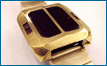
Synchronar MK2 Top and Bottom circuit board views
15 posts
• Page 1 of 1


![[IMG=http://img33.imageshack.us/img33/6455/imgp0018.gif][/IMG]](http://img33.imageshack.us/i/imgp0018.gif/)
15 posts
• Page 1 of 1
Who is online
Users browsing this forum: No registered users and 14 guests