Hi
I bought some time ago a Synchronar m1 watch. I'm so fascinated about the whole Synchronar story, so I decided to get one for me to.
The working watches are to expensive for me and I really like to repair led watches my self.
Before that I was reading almost every topic in synchronar forum in here.
So I carefully opend it up and there was a great amount of corrosion in the modul . I will put the pict up here to.
I think the modul is damaged too much and I can not save it.
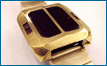
I have not yet taking of the top of the watch (solar cell) , so I dont know whats the situation in there. Probably not good.
I think the chip is gone, the damage is to great.
I think you all here have seen worst modules then this. Should I just let it go or try to save it ( perhaps new chip) and clean it up and test it?
Thank you
[/img]

Uploaded with
ImageShack.us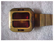


![[img]http://img25.imageshack.us/img25/2996/dscn2559small.th.jpg[/img]](http://img25.imageshack.us/i/dscn2559small.jpg/)
![[img]http://img10.imageshack.us/img10/3424/dscn2596small.th.jpg[/img]](http://img10.imageshack.us/i/dscn2596small.jpg/)
![[img]http://img97.imageshack.us/img97/7233/dscn2605small.th.jpg[/img]](http://img97.imageshack.us/i/dscn2605small.jpg/)
![[img]http://img826.imageshack.us/img826/6021/0000d.th.jpg[/img]](http://img826.imageshack.us/i/0000d.jpg/)