![]() 26 Sep 2010, 21:21
26 Sep 2010, 21:21
Hi guys, since this is my first post I think an introduction is in order: my name is Andrew, I live in Ohio, USA and for about 16 years I have had the Synchronar bug after picking some up second hand. For most of the time they have sat in a protected drawer but partially because of the good info available here I recently decided to pull them out and have a go at repair.
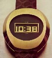
First, they are model (mark) 1 or 2's I think. One has a brushed stainless and the other has polished finish shell.
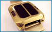
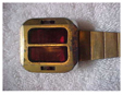
Inside they are quite different, but I see both circuits referred to as M1 here on the forum, which is a bit confusing. Can you clarify this? Here are top photos after a soak and clean in ronsonol lighter fluid to swell and remove the silicone encapsulant:
UNIT 1
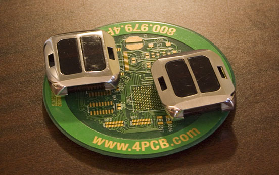
UNIT 2
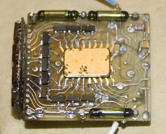
On the second pic I have already replaced the transistors as the old ones had corrosion and the epoxy bubble just barely lifting up under microscope inspection.
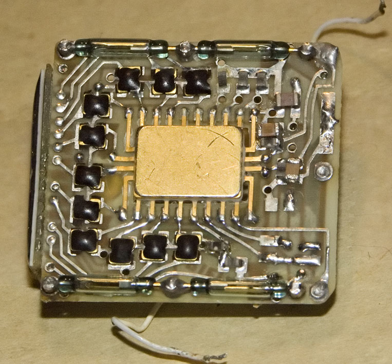
Bottom Views:
UNIT 1
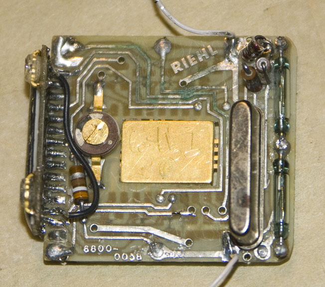
UNIT 2
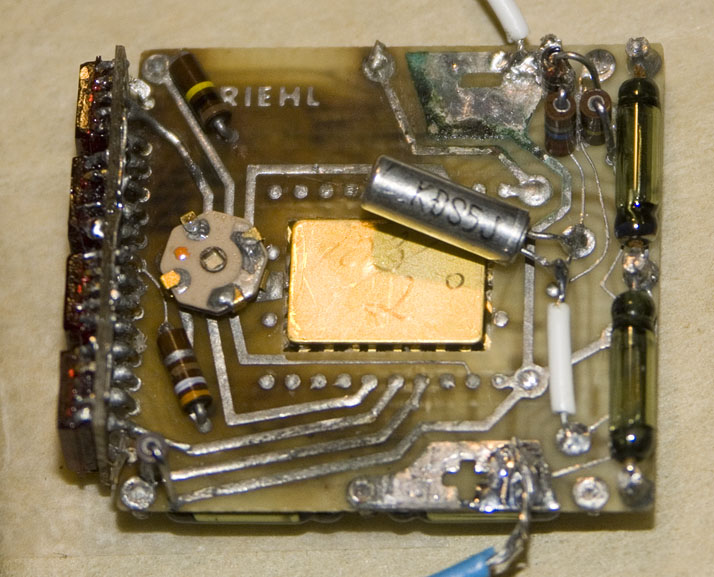
As you can see I had to replace the crystal on the second unit due to corrosion. Also this second unit has bad corrosion on the display segment leads, some of which have been eaten through.
Problems:
Unit 1:
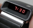
The first 'line LED display' unit is basically fully working and in great condition, except the IC has a problem of excessive bias on the seconds display selector pin. The 100k pull-down resistor here is insufficient and a 6.8k resistor is required to turn the seconds display off. This results in a 165 microAmp current draw while the unit is idling, instead of the typical 16 microAmp draw of a good unit. Also, the 'date' display comes on at full brightness and pulls 180mA, much brighter than the other modes.
So. I'm looking for a new IC for this unit.
Unit 2:
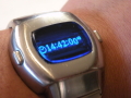
This 'dot matrix display' unit sustained widespread corrosion from battery juice, and has the crystal, transistors, and LED segment pins eaten. After replacing the transistors, most of the segments work I'm in the process of re-connecting the corroded segment leads where possible. It's a challenge because the segment plastic softens a lot when heated and can flex, leading to bond wire breakage internally. The one irreparable problem with this one is that the upper right segment output from the chip is very weak and can't turn on the transistor.
So, I'm looking for a good (or fixable) display for this unit and a replacement chip as well.
A few things I noticed, being a new member here. I see everyone referring to the sealant material as 'gel' or 'gooey stuff' but it IS just silicone elastomer, right?
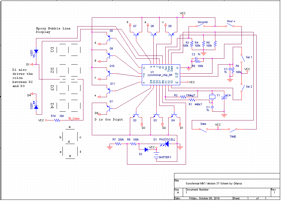
This diagram:
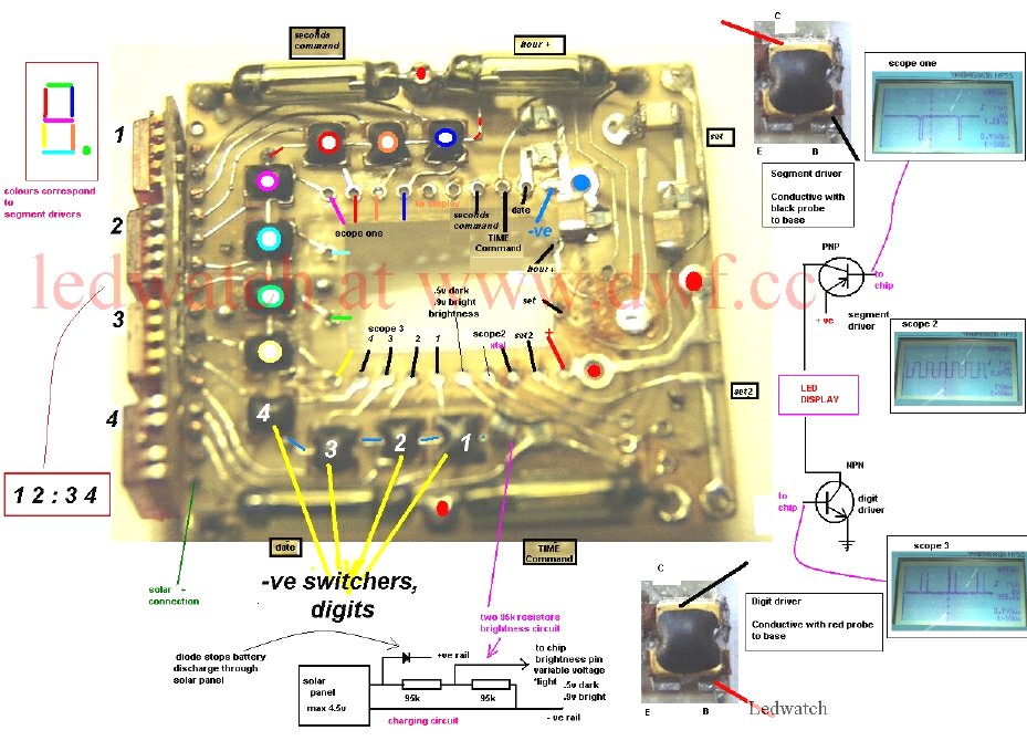
is very helpful, but the segment order is inaccurate for some watch types. it claims to originate from dwf.cc, but that forum only has 4 threads under the synchronar section and I don't see this image anywhere.
I have ordered some 'gooey guts' from Barry Riehl and hope that they will contain the parts I need, but if not, hopefully one of you will have these things?
One more thing I'm looking for is a rear setting spring/magnet; if you have one available for sale, please let me know!
Thank you for your many informative posts here, it has become a good source of info. I hope the admin backs up the forum once in a while to preserve this knowledge.
First, they are model (mark) 1 or 2's I think. One has a brushed stainless and the other has polished finish shell.
Inside they are quite different, but I see both circuits referred to as M1 here on the forum, which is a bit confusing. Can you clarify this? Here are top photos after a soak and clean in ronsonol lighter fluid to swell and remove the silicone encapsulant:
UNIT 1
UNIT 2
On the second pic I have already replaced the transistors as the old ones had corrosion and the epoxy bubble just barely lifting up under microscope inspection.
Bottom Views:
UNIT 1
UNIT 2
As you can see I had to replace the crystal on the second unit due to corrosion. Also this second unit has bad corrosion on the display segment leads, some of which have been eaten through.
Problems:
Unit 1:
The first 'line LED display' unit is basically fully working and in great condition, except the IC has a problem of excessive bias on the seconds display selector pin. The 100k pull-down resistor here is insufficient and a 6.8k resistor is required to turn the seconds display off. This results in a 165 microAmp current draw while the unit is idling, instead of the typical 16 microAmp draw of a good unit. Also, the 'date' display comes on at full brightness and pulls 180mA, much brighter than the other modes.
So. I'm looking for a new IC for this unit.
Unit 2:
This 'dot matrix display' unit sustained widespread corrosion from battery juice, and has the crystal, transistors, and LED segment pins eaten. After replacing the transistors, most of the segments work I'm in the process of re-connecting the corroded segment leads where possible. It's a challenge because the segment plastic softens a lot when heated and can flex, leading to bond wire breakage internally. The one irreparable problem with this one is that the upper right segment output from the chip is very weak and can't turn on the transistor.
So, I'm looking for a good (or fixable) display for this unit and a replacement chip as well.
A few things I noticed, being a new member here. I see everyone referring to the sealant material as 'gel' or 'gooey stuff' but it IS just silicone elastomer, right?
This diagram:
is very helpful, but the segment order is inaccurate for some watch types. it claims to originate from dwf.cc, but that forum only has 4 threads under the synchronar section and I don't see this image anywhere.
I have ordered some 'gooey guts' from Barry Riehl and hope that they will contain the parts I need, but if not, hopefully one of you will have these things?
One more thing I'm looking for is a rear setting spring/magnet; if you have one available for sale, please let me know!
Thank you for your many informative posts here, it has become a good source of info. I hope the admin backs up the forum once in a while to preserve this knowledge.
Last edited by drlava on 09 Feb 2016, 09:11, edited 1 time in total.