It is currently 08 Oct 2025, 00:08


P1 E/D Module Working (Kinda, Sorta)

  • Author
  • Message
Offline
User avatar

abem

Techno Mage

Techno Mage

  • Posts: 590
  • Joined: 17 Apr 2009, 05:10
  • Location: Madison, Wisconsin

P1 E/D Module Working (Kinda, Sorta)

Post11 Sep 2010, 21:55

Pulsar-fans,

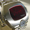
Over the past few months, I've come to the conclusion that there's almost certainly no P1 expert in existence to send a 25 chip E/D module to for repair and that it's probably ok for me to tinker with it a bit myself (see http://www.dwf.nu/viewtopic.php?t=4060). So this afternoon, with the autumn weather finally more conducive to tinkering, I took it out of its little box, put aside the fancy power supply that I used for the first round of tests and simply attached some leads from a 99 cent AA battery pack. There seems to be some connectivity issues and the module and it's not very consistent, but lo and behold, it works (kinda, sorta):

Dang, I should have waited 3 more minutes and photographed it at 12:08:
Enlarge (1200x1800): http://img822.imageshack.us/img822/78/d ... 0x1800.jpg
Image

Close-up of the display showing dashes:
Enlarge: (1800x1200): http://img825.imageshack.us/img825/3796 ... 0x1200.jpg
Image

A few observations:
1) The digits are composed of not dots or segments, but dashes
2) The display is shockingly bright - the digits are tiny but brighter than those on any other module that I have seen. I think I read somewhere that they are not multiplexed so perhaps that's the explanation?
3) One segment is a bit dimmer than the rest, but otherwise I think they are all working.
4) The quartz crystal / timing circuit may be working. The time seems to be advancing properly from minute to minute. It's hard to tell definitively because the operation is inconsistent and I haven't been able to run it long enough and consistently enough to be certain.

At this point, I think the next step is probably to see if I can get the battery connections fixed so I don't need to connect directly to the board and deal with fickle connectivity issues.

So, this all seems rather promising - all is not completely lost. Perhaps some day I will have a working P1.

-abe.
Offline
User avatar

bucko170

Guru

Guru

  • Posts: 3650
  • Joined: 20 Oct 2007, 11:47
  • Location: Nottinghamshire: The Home of Robin Hood..... UK

: P1 E/D Module Working (Kinda, Sorta)

Post11 Sep 2010, 22:16

Impressive 8-)

Should the 2 digit display beneath the main display show the seconds?

Good luck with the connectivity issue, loving the photo's please keep them coming.
Offline
User avatar

abem

Techno Mage

Techno Mage

  • Posts: 590
  • Joined: 17 Apr 2009, 05:10
  • Location: Madison, Wisconsin

: P1 E/D Module Working (Kinda, Sorta)

Post11 Sep 2010, 23:10

Yes, the little two digit display should show the seconds. Unfortunately, when I activate the seconds display, the ones digit looks completely dead and the tens digit stays on zero like this:
Image

I think I might have been overly optimistic in my initial assessment. Now, I don't think the crystal / clock is working because when I was able to keep it running for a few minutes the time display didn't change. Whenever I would inadvertantly break the circuit, the minutes advance, which gave me a false impression.

-abe.
Last edited by abem on 11 Sep 2010, 23:40, edited 1 time in total.
Offline

J Thomas

Wizard

Wizard

  • Posts: 410
  • Joined: 29 Jan 2008, 19:44

Re: : P1 E/D Module Working (Kinda, Sorta)

Post11 Sep 2010, 23:21

:-D
Last edited by J Thomas on 30 Mar 2011, 07:59, edited 1 time in total.
Offline
User avatar

abem

Techno Mage

Techno Mage

  • Posts: 590
  • Joined: 17 Apr 2009, 05:10
  • Location: Madison, Wisconsin

: P1 E/D Module Working (Kinda, Sorta)

Post11 Sep 2010, 23:43

Jeff,

That really interesting. Do you have a suggestion about the crystal specifics and where one might acquire a bar type crystal? I tried an ordinary tuning fork type crystal (just touching it to the contacts) and didn't see any change.

-abe.
Offline

J Thomas

Wizard

Wizard

  • Posts: 410
  • Joined: 29 Jan 2008, 19:44

Re: : P1 E/D Module Working (Kinda, Sorta)

Post12 Sep 2010, 07:12

:-D
Last edited by J Thomas on 30 Mar 2011, 08:00, edited 1 time in total.
Offline
User avatar

charger105

Guru

Guru

  • Posts: 867
  • Joined: 02 Mar 2007, 02:11
  • Location: Australia

: P1 E/D Module Working (Kinda, Sorta)

Post12 Sep 2010, 08:06

the original crystal would almost certainly need to be out of the circuit before another could be tested

You beat me to it Jeff :-)

Good to see this thing lit up Abe ! Once again, nice photos. Normally if the oscillator isn't working, a single digit will only be seen. But if this thing isn't multiplexed, then I guess you would see the whole display lit up.....just not incrementing. So, if it's definitely not incrementing, then it could certainly be the oscillator not running. Fingers crossed it's just the crystal......

Keep us posted Abe.
Rgds,
Andrew.
Offline

J Thomas

Wizard

Wizard

  • Posts: 410
  • Joined: 29 Jan 2008, 19:44

: P1 E/D Module Working (Kinda, Sorta)

Post16 Sep 2010, 21:07

:-D
Last edited by J Thomas on 30 Mar 2011, 08:00, edited 1 time in total.
Offline
User avatar

abem

Techno Mage

Techno Mage

  • Posts: 590
  • Joined: 17 Apr 2009, 05:10
  • Location: Madison, Wisconsin

: P1 E/D Module Working (Kinda, Sorta)

Post16 Sep 2010, 21:40

Hi Jeff,

I must not be searching correctly. I couldn't find any 32 KHz crystals that were not of the tuning fork type. For example, if you look at crystals on DigiKey, this is what you see:
http://search.digikey.com/scripts/DkSea ... Hz&x=0&y=0

Perhaps you have an idea of a source? Otherwise, would a 32KHz oscillator chip work (even thought it would be extremely un-vintage)?

-abe.

p.s. I really appreciate the help!
Offline

J Thomas

Wizard

Wizard

  • Posts: 410
  • Joined: 29 Jan 2008, 19:44

Re: : P1 E/D Module Working (Kinda, Sorta)

Post16 Sep 2010, 22:37

:-D
Last edited by J Thomas on 30 Mar 2011, 08:01, edited 1 time in total.
Offline
User avatar

abem

Techno Mage

Techno Mage

  • Posts: 590
  • Joined: 17 Apr 2009, 05:10
  • Location: Madison, Wisconsin

: P1 E/D Module Working (Kinda, Sorta)

Post16 Sep 2010, 23:45

Jeff,

Ah, I see - the light is slowly and dimly beginning to glow, so to speak. I've done crystal and reed switch swaps before, but I'm really a software guy so I'm quite out of my element. I'm beginning to get the idea. I'll probably re-enlist my electrical engineering friend to consult to make sure I get this right.

Thanks in particular for the advice about the 3V power supply. I've been rather nervous about frying the module and was wondering how to easily limit the current. This seems like a perfect solution.

I'm also wondering if I'm doing the right thing by connecting directly to the board? I worry about damaging the fine traces since they are so very delicate. I'd rather connect to the leads that connect the board to the battery terminals or to the battery contacts themselves. There seems to be a connectivity problem somewhere that shouldn't be too hard to track down.

One more daft question - should I be taking any special precautions about static electricity (especially now that fall is upon us and the air is dry once again)?

Many thanks, knowledgeable Master, from a wee grasshopper.

-abe.
Offline

J Thomas

Wizard

Wizard

  • Posts: 410
  • Joined: 29 Jan 2008, 19:44

Re: : P1 E/D Module Working (Kinda, Sorta)

Post17 Sep 2010, 00:21

:-D
Last edited by J Thomas on 30 Mar 2011, 08:01, edited 1 time in total.
Offline

USBitsa

Member

Member

  • Posts: 18
  • Joined: 04 Jan 2011, 03:37
  • Location: California

Re: : P1 E/D Module Working (Kinda, Sorta)

Post13 Jan 2011, 23:53

abem wrote:Jeff,

Ah, I see - the light is slowly and dimly beginning to glow, so to speak. I've done crystal and reed switch swaps before, but I'm really a software guy so I'm quite out of my element. I'm beginning to get the idea. I'll probably re-enlist my electrical engineering friend to consult to make sure I get this right.

Thanks in particular for the advice about the 3V power supply. I've been rather nervous about frying the module and was wondering how to easily limit the current. This seems like a perfect solution.

I'm also wondering if I'm doing the right thing by connecting directly to the board? I worry about damaging the fine traces since they are so very delicate. I'd rather connect to the leads that connect the board to the battery terminals or to the battery contacts themselves. There seems to be a connectivity problem somewhere that shouldn't be too hard to track down.

One more daft question - should I be taking any special precautions about static electricity (especially now that fall is upon us and the air is dry once again)?

Many thanks, knowledgeable Master, from a wee grasshopper.

-abe.


Abe !!

WOW ! I just saw this and.... i love it ! Great to see !

Good call by Jeff to current limit the supply too !

I read your words and crapped myself when you had mentioned how bright the LED's are tho !!

The "Nominal Voltage" of an Alkaline Cell is 1.5volts (two in series 3.0 volts).

Nominal voltage of the original cells (i'm thinking they would have been Mercury Cells) was much lower, if memory serves me... only 1.01 or 1.2volts !

So, you could be putting as much as a volt in excess of max. on the little CMOS circuits by using the two AA alkaline cells to power it ?

Jeff is also correct it that there is no protection on the early CMOS semi's, they are "Un-Bufferred" and are as such very sensitive to static ! far more than you may think ! I used to design with the early RCA Cmos... "POP ! oops ! it stopped working" was a common occurrence in the lab ! easy back then, change the chip and move on....

Keep it going man ! love seeing this lovely old thing running !!

Best of luck !

ps... it may even run happily on just a single 1 AA cell ?
LED graveyard here !
Offline
User avatar

abem

Techno Mage

Techno Mage

  • Posts: 590
  • Joined: 17 Apr 2009, 05:10
  • Location: Madison, Wisconsin

: P1 E/D Module Working (Kinda, Sorta)

Post15 Jan 2011, 07:42

Thanks for the kind words and encouragement.

Yes, I sure would be something to see it fully working again, especially now that the case has been restored: http://www.dwf.nu/viewtopic.php?t=4322

I've been reluctant to tinker with it during the past few months since at my wintery Northerly lattitude it is currently quite dry and easy to generate significant static charges. Twice in the past two weeks I've touched my computer resulting in an audible static shock strong enough to cause it to reboot - even in a house free of carpets!

I could take precautions, but I'd hate to wreck this module because of carelessness. So, for the time being, I'll probably leave the module be and focus on getting the case back in presentable order. I perhaps may look into making a P1 sized carrier for a P2 module.

-abe.

Return to Pulsar and Hamilton

Who is online

Users browsing this forum: No registered users and 8 guests