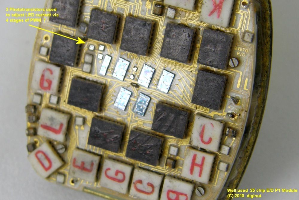
Thanks for the great comments on the photos. I've been photographing the module for historical documentation purposes, but there is a sort of beauty in the precision and layout of the module wiith its tiny hand assembled board and 25 tiny ICs. The first person that I showed the images to (who used to be an electrical engineer) said "They are works of art in their own right... perhaps a print for the wall?".
If anyone wants higher resolution images for prints, just email me. The 1800x1200 images are probably good enough to print, but there's a little more detail available at 3600x2400.
On to responses:
Old Tom:
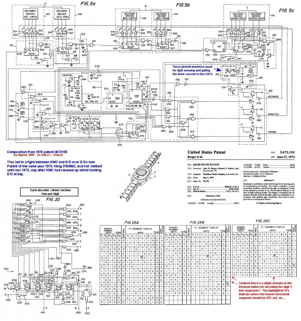
I would be really interested to hear the functions of each of the 25 chips. If you could post some info or a link to information about the chip layout, that would be swell. I downloaded the original Bergey patent to see if that offered some clues, but most of the text and diagrams are abstract or geared to the prototype module:
http://www.freepatentsonline.com/3672155.pdf
bucko170:
I haven't tried to power it up yet (It's tempting!). It should be easy enough to do - just connect to the two leads shown in the left view image, however I'm still trying to find out if I should be limiting current and voltage when I do it and by how much. I've been told that this is not really necessary, but I have also read an opinion that it is (see Archer MacClean's account here:
http://www.dwf.cc/viewtopic.php?f=26&t=372&start=0), so I'd like to make sure. I have an electrical engineering friend who has the proper equipment, so I should be able to do this the right way.
Incidentally, I emailed the seller last week (I've been keeping in touch with him) and asked him when it was last working. He said "i would say keep your fingers crossed on it working it was working when i took the batteries out of it." So, that's intriging! Just think, not long ago there was a guy walking around wearing a P1 using the original 25 chip module. Imagine running into someone in a line at the supermarket and asking for the time, only to look over and see a P1 with a glowing 6 digit display!
Klippie:
I'll see if I can get a shot of the underside of the PCB. It's mostly hidden behind the mount / battery holder, but I'll see what I can do. Yes, the board looks remarkably clean. I'm glad that this module has the chips and their letters all visible in white and red. Some of the modules had the chips surrounding the display colored over with black ink to hide them under the display.
Charger105:
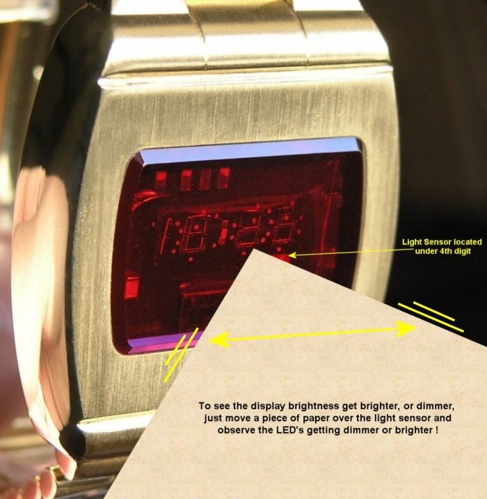
Great observation - I forgot to mention that. Yes, underneath the display is a piece of transparent purple-blue acetate. Apparently, they were still experimenting with the filter color. I've thought about replating the case and a collector has even offered to help me with it, but I actually have grown to like the nickel-silver color so I'm inclined to keep it unplated.
Jeff Thomas:
After hearing that the seller's father worked for American Time and Temp (a division of E/D), I'm really curious about what was going on at Electro Data in mid to late 1971. You say that they closed in 1979, but I've read that they closed the time division in 1973 which makes me wonder what the atmosphere was like where P1s would be given out to employees. That list of documents is impressive - who would have guessed! I'll have to study this in more detail - the University of Minnesota is just a day trip away for me.
-abe.


.jpg)
.jpg)


