It is currently 07 Oct 2025, 17:33


P1 Module Exposed!

  • Author
  • Message
Offline
User avatar

abem

Techno Mage

Techno Mage

  • Posts: 590
  • Joined: 17 Apr 2009, 05:10
  • Location: Madison, Wisconsin

P1 Module Exposed!

Post01 May 2010, 06:24

Pulsar fans,

Over the past few weeks, I've been carefully removing the epoxy that was used to close my nickel silver P1 case. Last week, I was finally able to open the case and to view the original module concealed inside.

Below are a set of images documenting the intricate and delicate 25 chip module. Enjoy!

Case and Module:
Enlarge: http://img217.imageshack.us/img217/4807 ... ule180.jpg
Image

Front View:
Enlarge: http://img688.imageshack.us/img688/6748 ... 0x1800.jpg
Image

Oblique Right View:
Enlarge: http://img203.imageshack.us/img203/3057 ... ht1800.jpg
Image

Oblique Left View:
Enlarge: http://img203.imageshack.us/img203/3398 ... t1800x.jpg
Image

Bottom View:
Enlarge: http://img697.imageshack.us/img697/7301 ... 0x1200.jpg
Image

Right View:
Enlarge: http://img688.imageshack.us/img688/7316 ... 0x1200.jpg
Image

Top View:
Enlarge: http://img227.imageshack.us/img227/5088 ... 0x1200.jpg
Image

Left View:
Enlarge: http://img227.imageshack.us/img227/6969 ... 0x1200.jpg
Image

Display, Oblique View:
Enlarge: http://img406.imageshack.us/img406/1236 ... ique18.jpg
Image

Copyright Notice:
Enlarge: http://img688.imageshack.us/img688/8647 ... 800x12.jpg
Image

Patent Pending:
Enlarge: http://img406.imageshack.us/img406/2838 ... ing180.jpg
Image

Display, Front:
Enlarge: http://img265.imageshack.us/img265/9357 ... nt1800.jpg
Image

-abe.
Offline
User avatar

Old Tom

Wizard

Wizard

  • Posts: 274
  • Joined: 15 Dec 2006, 10:48
  • Location: London, England

: P1 Module Exposed!

Post01 May 2010, 09:29

What beautiful and invaluable pictures! You could almost certainly reverse engineer the entire circuit diagram from these pics- previously only the function/type of the B & C chips has eluded me during one of my "back of an envelope what chip is that" ponderings on the inner workings of the P1 and I think I know what they are now.
Offline
User avatar

bucko170

Guru

Guru

  • Posts: 3650
  • Joined: 20 Oct 2007, 11:47
  • Location: Nottinghamshire: The Home of Robin Hood..... UK

: P1 Module Exposed!

Post01 May 2010, 10:32

Fantastic photographs thanks for posting them.

Any signs of life from the module or have you spotted any obvious defects?
Offline
User avatar

Led-Time

Guru

Guru

  • Posts: 971
  • Joined: 05 Jun 2005, 00:28
  • Location: Scotland

: P1 Module Exposed!

Post01 May 2010, 12:40

Brilliant series of shots there Abe... 8-)

The PCB looks unbelievably clean, would it be possible to test all the surface mount components just in case its a simple fix to get this wonder up and running again.

Could you manage to get a shot of underneath the PCB I'am curious to see what else is under there.
Offline
User avatar

charger105

Guru

Guru

  • Posts: 867
  • Joined: 02 Mar 2007, 02:11
  • Location: Australia

: P1 Module Exposed!

Post01 May 2010, 15:18

Marvelous shots Abe.

Is that some sort of blue filter on the underside of the red crystal ?
Now that it's apart, are you going to get the case replated ?

Rgds,
Andrew.
Offline

J Thomas

Wizard

Wizard

  • Posts: 410
  • Joined: 29 Jan 2008, 19:44

: P1 Module Exposed!

Post01 May 2010, 16:48

:-D
Last edited by J Thomas on 30 Mar 2011, 05:35, edited 1 time in total.
Offline
User avatar

abem

Techno Mage

Techno Mage

  • Posts: 590
  • Joined: 17 Apr 2009, 05:10
  • Location: Madison, Wisconsin

: P1 Module Exposed!

Post01 May 2010, 20:39

Thanks for the great comments on the photos. I've been photographing the module for historical documentation purposes, but there is a sort of beauty in the precision and layout of the module wiith its tiny hand assembled board and 25 tiny ICs. The first person that I showed the images to (who used to be an electrical engineer) said "They are works of art in their own right... perhaps a print for the wall?".

If anyone wants higher resolution images for prints, just email me. The 1800x1200 images are probably good enough to print, but there's a little more detail available at 3600x2400.

On to responses:

Old Tom:
I would be really interested to hear the functions of each of the 25 chips. If you could post some info or a link to information about the chip layout, that would be swell. I downloaded the original Bergey patent to see if that offered some clues, but most of the text and diagrams are abstract or geared to the prototype module: http://www.freepatentsonline.com/3672155.pdf

bucko170:
I haven't tried to power it up yet (It's tempting!). It should be easy enough to do - just connect to the two leads shown in the left view image, however I'm still trying to find out if I should be limiting current and voltage when I do it and by how much. I've been told that this is not really necessary, but I have also read an opinion that it is (see Archer MacClean's account here: http://www.dwf.cc/viewtopic.php?f=26&t=372&start=0), so I'd like to make sure. I have an electrical engineering friend who has the proper equipment, so I should be able to do this the right way.

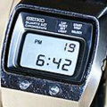
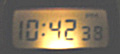
Incidentally, I emailed the seller last week (I've been keeping in touch with him) and asked him when it was last working. He said "i would say keep your fingers crossed on it working it was working when i took the batteries out of it." So, that's intriging! Just think, not long ago there was a guy walking around wearing a P1 using the original 25 chip module. Imagine running into someone in a line at the supermarket and asking for the time, only to look over and see a P1 with a glowing 6 digit display!

Klippie:
I'll see if I can get a shot of the underside of the PCB. It's mostly hidden behind the mount / battery holder, but I'll see what I can do. Yes, the board looks remarkably clean. I'm glad that this module has the chips and their letters all visible in white and red. Some of the modules had the chips surrounding the display colored over with black ink to hide them under the display.

Charger105:
Great observation - I forgot to mention that. Yes, underneath the display is a piece of transparent purple-blue acetate. Apparently, they were still experimenting with the filter color. I've thought about replating the case and a collector has even offered to help me with it, but I actually have grown to like the nickel-silver color so I'm inclined to keep it unplated.

Jeff Thomas:
After hearing that the seller's father worked for American Time and Temp (a division of E/D), I'm really curious about what was going on at Electro Data in mid to late 1971. You say that they closed in 1979, but I've read that they closed the time division in 1973 which makes me wonder what the atmosphere was like where P1s would be given out to employees. That list of documents is impressive - who would have guessed! I'll have to study this in more detail - the University of Minnesota is just a day trip away for me.

-abe.
Offline
User avatar

morelite

Techie

Techie

  • Posts: 148
  • Joined: 18 Mar 2010, 01:50
  • Location: Central PA

: P1 Module Exposed!

Post02 May 2010, 02:05

Outstanding pics
You must be able to fight temptation far better than me, I would have tried powering it up right away. :-)
Offline
User avatar

retroleds

Guru

Guru

  • Posts: 3634
  • Joined: 04 Feb 2006, 10:34
  • Location: Surrounded by hicks and sticks (farms and woods) - Michigan,USA

: P1 Module Exposed!

Post02 May 2010, 21:15

Stunning Abe. You have made a lot of Pulsar fans very happy. Thank you for posting here. 8-)
http://www.retroleds.com - Sales of vintage LED, LCD, analog watches, parts and gadgets - repair tutorials & tips
Nov. 2022 - back in business!! BItter divorce is in home stretch, come grabs some great deals, I had to open the safe . . . damn attorneys. piss.
Offline

f.e.a.r

Techie

Techie

  • Posts: 144
  • Joined: 14 Mar 2006, 22:29

: P1 Module Exposed!

Post03 May 2010, 00:52

well done abe, glad you got that back off. great pics. much better than leaving it locked away.
Offline
User avatar

LEDluvr

Guru

Guru

  • Posts: 1001
  • Joined: 06 Jun 2007, 22:49
  • Location: Los Angeles

: P1 Module Exposed!

Post03 May 2010, 19:29

Awesome pics Abe! I'm glad you got this jem and not just 'some guy' outside of the community who would not give this the treatment (and documentation) it deserves. I couldn't blame you for printing up a small poster of one or more of the pics.

Now the next step is... lets see if it comes to life! :!:
Offline
User avatar

bucko170

Guru

Guru

  • Posts: 3650
  • Joined: 20 Oct 2007, 11:47
  • Location: Nottinghamshire: The Home of Robin Hood..... UK

: P1 Module Exposed!

Post30 May 2010, 23:07

Abe :: Any updates on the working condition of the watch?
Offline

Handy

Techie

Techie

  • Posts: 124
  • Joined: 14 Jan 2005, 14:17
  • Location: Stoke-on-Trent,England.

: P1 Module Exposed!

Post31 May 2010, 00:10

I'd be interested too. :-)
Offline
User avatar

napnap

Nerd

Nerd

  • Posts: 46
  • Joined: 09 Apr 2012, 02:29
  • Location: Montreal, Quebec

Re: P1 Module Exposed!

Post29 May 2012, 04:12

This is beautiful! A 2010 post but still no conclusion on the outcome of powering up the module!
Is it alive?
Offline
User avatar

abem

Techno Mage

Techno Mage

  • Posts: 590
  • Joined: 17 Apr 2009, 05:10
  • Location: Madison, Wisconsin

Re: P1 Module Exposed!

Post29 May 2012, 07:05

Hi.

I haven't tinkered with it for over a year. The last time I checked, the conclusion was that the display driver electronics were working but for some reason it does not appear to be clocking. It could be a quartz crystal issue or (more likely) it could be something more significant. So, yes, it displays digits, but the time does not advance:

Image

Image

I've resisted he urge to tinker with it further until I can find someone qualified to help since I don't want to risk damaging it. So, for now, it sits in its little box waiting patiently...

-abe.
Offline
User avatar

70's_gal

Geek

Geek

  • Posts: 81
  • Joined: 22 Feb 2004, 19:37
  • Location: Vancouver Island, Canada

Re: P1 Module Exposed!

Post29 May 2012, 20:35

No idea how I missed this thread, but it's amazing! Excellent photography! Thanks so much for sharing this.

~Sherry.
Too many watches, not enough wrists... ;-)
Offline
User avatar

charger105

Guru

Guru

  • Posts: 867
  • Joined: 02 Mar 2007, 02:11
  • Location: Australia

Re: P1 Module Exposed!

Post12 Apr 2013, 14:10

I was reading through the P1 manual that came with your watch Abe, and it mentioned the light-sensor function.
Is there actually a light-sensor on this module ? There doesn't seem to be one that I recognise ?

The manual has been written for the 25-IC module (i.e. seconds displayed below the time in the pictures), so I don't think the manual is referencing the later P2 modules that were transplanted into most of them (which obviously did have a light sensor).

Rgds.
Offline
User avatar

abem

Techno Mage

Techno Mage

  • Posts: 590
  • Joined: 17 Apr 2009, 05:10
  • Location: Madison, Wisconsin

Re: P1 Module Exposed!

Post12 Apr 2013, 16:52

Hi.

Nice job pointing that out. I never noticed that in the manual before. I find it impressive that they incorporated so much functionality in the first module - seconds display, light sensor. You might think that they'd be happy just to get it working (feature creep alert).

The light sensor is the white vertical rectangle to the left of the "1" digit in the hours display. I wonder what the two little black squares above and to the right of it are for?

Cheers,

-abe.
Offline
User avatar

charger105

Guru

Guru

  • Posts: 867
  • Joined: 02 Mar 2007, 02:11
  • Location: Australia

Re: P1 Module Exposed!

Post13 Apr 2013, 01:14

Hi Abe.
Those little white squares look like normal SMT resistors to me :scratch:
Not sure what those black squares are. At first I thought AM/PM indicators, but don't think so now. Maybe these black squares are light sensors ?
Rgds.
Offline
User avatar

abem

Techno Mage

Techno Mage

  • Posts: 590
  • Joined: 17 Apr 2009, 05:10
  • Location: Madison, Wisconsin

Re: P1 Module Exposed!

Post13 Apr 2013, 07:34

Charger,

Hmm, yes, you're right! The two little white squares are about the same size and shape as a normal light sensor but upon closer inspection they do look just like two of the other little white surface mount resistors on the board placed next to each together.

Well, I don't know. Hopefully someone else with some actual 1970s era electrical engineering experience can chime in.

There's also another little black square to the left of the "1" IC that is a possible candidate.

-abe.
Offline
User avatar

Diginut

Techie

Techie

  • Posts: 238
  • Joined: 07 Jan 2006, 16:52
  • Location: Area 51, UK

Re: P1 Module Exposed!

Post17 Apr 2013, 16:40

.

I’d like to offer some input on this old debate !


Basically, as far as I can tell from the E/D P1 schematic, the 25 chip module used 3 photo transistors to adjust the brightness, not LDR's. Their on/off function had the combined logical effect of adjusting the amount of LED on/off current to provide 4 stages of brightness, from 100% full on, to 87.5% on, to 75% on, to 50% half-on, made out of combined 256/128/64 hz 50:50 square wave pulses from the 32khz divider train. See the attached circuit for LS1, LS2, LS3 and associated NAND and NOR gates.

I've used an old photo below of a 25 chip module I used to own (non functional unfortunately) to highlight the three SMD phototransistors to the upper left of the hours digit, near enough to the display to be under the sapphire and detect useful amounts of ambient light.

Later P1 and P2 modules have a different brightness adjustment process using a single LDR - visible as a long skinny SMD resistor with a wiggly track on it to the right of the digits !

You can easily test the light sensing in action on later P1 and P2 modules simply by moving the edge of a credit card back and forth over the right hand side of the red lens - the brightness will appear to go up/down ! (see illustration below)

I studied the 1970 HWC patent a couple of years ago, and somehow spotted a minor mistake in the patent for the boolean decoding of the digit '4' into segments. If the segments for '4' would have lit up as originally filed, you'd get a segmented ' y ' not a '4'.


Image

Image

Image
Last edited by Diginut on 19 Apr 2013, 11:57, edited 2 times in total.
Offline
User avatar

charger105

Guru

Guru

  • Posts: 867
  • Joined: 02 Mar 2007, 02:11
  • Location: Australia

Re: P1 Module Exposed!

Post18 Apr 2013, 11:55

Interesting. Thanks Diginut. I really didn't think anyone would know for sure.
Those 3 black squares were one of the candidates we had in mind. So these photo-transistors operate logically/digitally as opposed to the LDR resistor used in the later modules. Do the LDRs used in the later/normal Pulsar modules produce discreet light levels (I've got in the back of my mind thet they do), or does the display brightness vary smoothly through it's range ?

BTW, nice work debugging their boolean code :lol:
I presume they discovered it before production began !
Rgds.
Next

Return to Pulsar and Hamilton

Who is online

Users browsing this forum: No registered users and 13 guests